
Amici – block-based programming environment for Arduino
Amici – a Visual Block-Based Programming Language for Arduino
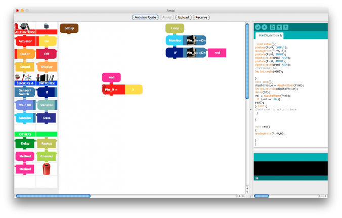
Amici is a visual programming language which enables programming novices to program Arduino boards without having to master the textual programming language Arduino .
Amici is based on the Arduino IDE. In other words, it enhances the Arduino IDE with a block-based visual interface. You can switch between views, and once you assemble your program with blocks you can watch how the textual code is generated.
Since the Arduino software is open-source Amici is open as well (source code on request), released under the GPL.
The support and development of Amici was discontinued in 2014.
Amici is available for Windows and Mac OS and has been translated to several languages (English, German, French, Spanish, Portuguese, Danish, Dutch).
The final releases are available for download (based on Arduino 1.0.5):
Amici 1.0 r German version for Windows
Amici 1.0 r German version for Mac
Amici 1.0 r Danish version for Windows
Amici 1.0 r Danish version for Mac
Amici 1.0 r English version for Windows
Amici 1.0 r English version for Mac
Amici 1.0 r Portuguese version for Windows
Amici 1.0 r Portuguese version for Mac

Einfaches Programm mit Amici
Amici has been developed by researchers of Dimeb (Digitale Media in Education) at the University of Bremen as part of the European project EduWear. The software been used in more than 40 workshops by children and young people.
Other resources:
- Manual: Getting started with the EduWear kit and Amici
- Anleitung „Fieberteddy“
- Anleitung „Zauberhafte Kleidung“